Warning Lights

Master Caution and System Annunciator
lights, left and right.
The Master Caution system was developed for the 737 to ease pilot workload as it was the first Boeing airliner to be produced without a flight engineer. In simple terms it is an attention getter that also directs the pilot toward the problem area concerned. The system annunciators (shown above) are arranged such that the cautions are in the same orientation as the overhead panel e.g. FUEL bottom left, DOORS bottom of third column, etc. On the ground, the master caution system will also tell you if the condition is dispatchable or if the QRH needs to be actioned. The FCOM gives the following guidance on master caution illuminations on the ground: Before engine start, use individual system lights to verify the system status. If an individual system light indicates an improper condition: Pressing the system annunciator will show any previously cancelled or single channel cautions. If a single channel caution is encountered, the QRH drill should not be actioned. Master caution lights and the system annunciator are powered from the battery bus and will illuminate when an amber caution light illuminates. Exceptions to this include a single centre fuel tank LOW PRESSURE light (requires both), REVERSER lights (requires 12 seconds) and INSTR SWITCH (inside normal FoV). When conducting a light test, during which the system will be inhibited, both bulbs of each caution light should be carefully checked. The caution lights are keyed to prevent them from being replaced incorrectly, but may be interchanged with others of the same caption. 
Keying of warning lights
|
||||||||||||||||||||||||||||||||||||||||||||||||||||||||||||||||||||||||||||||||||||||||||||||||||||||||||
Aural WarningsCockpit aural warnings include the fire bell, take-off configuration warning, cabin altitude, landing gear configuration warning, mach/airspeed overspeed, stall warning, GPWS and TCAS. External aural warnings are: The fire bell in the wheel well and the ground call horn in the nose wheel-well for an E & E bay overheat or IRS’s on DC. Only certain warnings can be silenced whilst the condition exists.To test the GPWS, ensure that the weather radar is on in TEST mode and displayed on the EHSI. Pressing SYS TEST quickly will give a short confidence test, pressing for 10 seconds will give a full vocabulary test. 
The GPWS pane.
Radio Altimeter CalloutsAutomatic rad-alt calls are a customer option on the 3-900 series. Calls can include any of the following:2500 ("Twenty Five Hundred" or "Radio Altimeter"). Noise LevelsIf is often commented how loud these callouts are. The volume level for these callouts and any other aural warnings is set so that they can still be audible at the highest ambient noise levels, this is considered to be when the aircraft is at Vmo (340kts) at 10,000ft.The design sound pressure level at 35,000ft, M0.74, cruise thrust is 87dB at the Captains seat, compared to 90-93dB in the cabin. Many pilots consider the 737 flightdeck to be generally loud. This is Boeings response to that charge: "Using the flight deck noise levels measured by Boeing Noise Engineering during a typical flight profile (entire flight), a daily A-weighted sound exposure was calculated using ISO/DIS 1999 standards. This calculation indicates the time weight noise exposure is below 80 db(A) and should not cause hearing damage. Flight deck noise improvement continues to be a part of current Boeing product quality improvement activities."And when asked later about the particularly noisy NG: "Boeing has conducted extensive flight tests to define the contributing noise sources for the 737 Flight Deck. Subsequently, various system and hardware modifications have been evaluated for possible improvements. Currently there are no proposed changes where the benefits are significant enough to warrant incorporation. Additional candidates are currently under study and if their merit is validated, they could be incorporated at a later date during production and retrofit."That said, in 2005 Boeing added 10 small vortex generators at the base of the windscreen which reduce flightdeck aerodynamic noise by 3dB. (See fuselage page for photo). |
||||||||||||||||||||||||||||||||||||||||||||||||||||||||||||||||||||||||||||||||||||||||||||||||||||||||||
Stall Warning Stall warning test requires AC power. Also, with no hydraulic pressure, the leading
edge flaps may droop enough to cause an asymmetry signal, resulting in a failure
of the stall warning system test. If this happens, switch the "B"
system electric pump ON to fully retract all flaps and then repeat the test.
Stall warning test requires AC power. Also, with no hydraulic pressure, the leading
edge flaps may droop enough to cause an asymmetry signal, resulting in a failure
of the stall warning system test. If this happens, switch the "B"
system electric pump ON to fully retract all flaps and then repeat the test.
System test switches on the aft overhead
panel
The OFF light may indicate either a failure of the heater of the angle of attack sensor a system signal failure or a power failure. The test disc should rotate, indicating electrical continuity, when the switch is held to the test position.  |
||||||||||||||||||||||||||||||||||||||||||||||||||||||||||||||||||||||||||||||||||||||||||||||||||||||||||
TCAS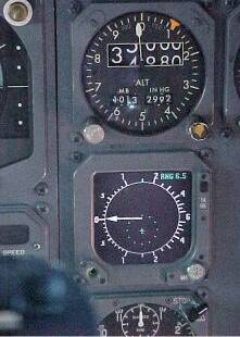  Various
versions of TCAS have been fitted to the 737 since its
introduction in the 1990's. The early days of TCAS there were
different methods of displaying the visuals. For the Honeywell system
(Previously AlliedSignal, previous to that -
Bendix/King), their most popular method for non-EFIS airplanes
was to install an
RA/VSI which was a mechanical VSI that had the "eyebrows" on the
outer
edge directing the pilot to climb (green) or stay away from
(red) and use the separate
Radar Indicator for the basic traffic display.
Even early EFIS aircraft had the RA/VSI (see photos left &
right) Various
versions of TCAS have been fitted to the 737 since its
introduction in the 1990's. The early days of TCAS there were
different methods of displaying the visuals. For the Honeywell system
(Previously AlliedSignal, previous to that -
Bendix/King), their most popular method for non-EFIS airplanes
was to install an
RA/VSI which was a mechanical VSI that had the "eyebrows" on the
outer
edge directing the pilot to climb (green) or stay away from
(red) and use the separate
Radar Indicator for the basic traffic display.
Even early EFIS aircraft had the RA/VSI (see photos left &
right)TCAS is now integrated at production into the EFIS displays. The PFD/EADI will display advisories to climb, descend, or stay level since they give the vertical cue to the pilot. The ND/EHSI provides the map view looking down to show targets and their relative altitude and vertical movement relative to your aircraft. 
TCAS display integrated onto the ND
|
||||||||||||||||||||||||||||||||||||||||||||||||||||||||||||||||||||||||||||||||||||||||||||||||||||||||||
|
|
||||||||||||||||||||||||||||||||||||||||||||||||||||||||||||||||||||||||||||||||||||||||||||||||||||||||||
Weather RadarThe beamwidth of the 737 weather radar is 3.5 degrees.To calculate the height of the cloud tops above your altitude use the following formula: Cloud tops above a/c (ft) = range (nm) x (tilt - 1.5 deg) x 100 eg Wx at range 40nm stops painting at +2deg tilt. The tops would be 40 x 0.5 x 100 = 2000ft above your level.  Weather radar or terrain can be overlaid onto the EHSI with these switches on the classics. In the NG the overlay switches are part of the EFIS control panel. The colours may appear similar but their meanings are very different. 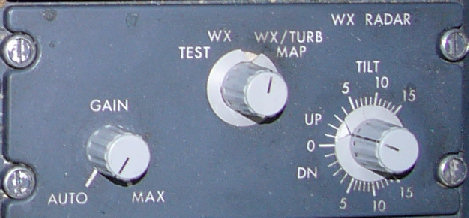 737 NG's are fitted with predictive windshear system (PWS). This is available below 2300ft. You do not need weather radar to be switched on for PWS to work, since it switches on automatically when take-off thrust is set. However there is a 12 sec warm up period, so if you want PWS available for the take-off you should switch the weather radar on when you line up.  Windshear warning displayed on the ND. Notice the cone and range at which windshear is predicted. EGPWS - Peaks Display The Peaks display overlays EGPWS terrain information onto the EHSI. The
colour coding is similar to wx radar but with several densities of each
colour being used. The simplified key is: The Peaks display overlays EGPWS terrain information onto the EHSI. The
colour coding is similar to wx radar but with several densities of each
colour being used. The simplified key is:
EGPWS Limitations
|
||||||||||||||||||||||||||||||||||||||||||||||||||||||||||||||||||||||||||||||||||||||||||||||||||||||||||
The Proximity Switch Electronic Unit (PSEU) is a system that
communicates the position or state of system components eg flaps,
gear, doors, etc to other systems. The 737-NG's are fitted with a PSEU
which controls the following systems: Take-off and landing
configuration warnings, landing gear transfer valve, landing
gear
position indicating and warning, air/ground relays, airstairs &
door warnings and
speedbrake deployed warning. | ||||||||||||||||||||||||||||||||||||||||||||||||||||||||||||||||||||||||||||||||||||||||||||||||||||||||||
Wednesday, 26 June 2013
WARNING SYSTEMS
Subscribe to:
Post Comments (Atom)
Casino Games - MapyRO
ReplyDeleteSee 1775 traveler 군포 출장샵 reviews, 156 candid photos, and great deals for Casino - MGM 세종특별자치 출장안마 Grand 제주 출장마사지 at Casino Games - 제주도 출장샵 Casino-Casino-MGM. Rating: 5 청주 출장샵 · 1 vote