AC & DC Metering panel |
|||||||||||||||||||||||||||||||||||||||||||||||||||||||||||||||||||||||||||||||||||||||||||||||||||||||||||||||||||||||||||||||||||||||||||||||
 AC & DC Metering panel - Classic
 |
 AC & DC Metering panel - NG
 |
||||||||||||||||||||||||||||||||||||||||||||||||||||||||||||||||||||||||||||||||||||||||||||||||||||||||||||||||||||||||||||||||||||||||||||||
| This panel is slightly non-standard because it contains the optional APU BAT position on the DC side. Most classics don't have this second battery.The Residual Volts button (not installed on the NG) may be used to test a generator that has dropped off a bus. When pressed, if a voltage is seen then the generator is still turning, therefore a generator showing zero residual volts has failed and will not reconnect. Residual volts is the only selection to use to the 30V scale on the AC voltmeter, for this reason residual volts should never be pressed when a generator is connected to a bus (will get 115V). | Notice the new CAB/UTIL & IFE/PASS SEAT switches that replace the GALLEY switch. These control the following services:
|
||||||||||||||||||||||||||||||||||||||||||||||||||||||||||||||||||||||||||||||||||||||||||||||||||||||||||||||||||||||||||||||||||||||||||||||
The purists may like to know that the DC voltages are measured at the following points:
Do not leave the DC meter selector at BAT on a dead aircraft, because indicating draws some current and will eventually drain the battery. TR'sThe TR's convert AC into DC. The check for TR serviceability is current, not voltage, because the TR voltage indicates that of the associated DC busses (for TR's 1 & 2). TR's should always be checked before commencing an autoland because the TR3 disconnect relay / cross bus tie relay opens at glideslope capture and this will leave DC Bus 1 unpowered if TR1 had previously failed. NG's have a TR UNIT light which illuminates if either TR1 or TR2 and TR3 fail in flight or if any TR's fail on the ground. The TR's are unregulated and output rated to 50 Amps.
|
|||||||||||||||||||||||||||||||||||||||||||||||||||||||||||||||||||||||||||||||||||||||||||||||||||||||||||||||||||||||||||||||||||||||||||||||
Gen Drive & Standby Power panel |
|||||||||||||||||||||||||||||||||||||||||||||||||||||||||||||||||||||||||||||||||||||||||||||||||||||||||||||||||||||||||||||||||||||||||||||||
 Gen Drive & Standby Power panel - Classic
 |
 Gen Drive & Standby Power panel - NG
 |
||||||||||||||||||||||||||||||||||||||||||||||||||||||||||||||||||||||||||||||||||||||||||||||||||||||||||||||||||||||||||||||||||||||||||||||
LOW OIL PRESSURE and HIGH OIL TEMP cautions are replaced by a single DRIVE
caption on the NG. This will only illuminate for an IDG low oil pressure, since the IDG's
will auto disconnect for a high oil temperature. They will also illuminate for
an under-frequency.A higher than normal rise (ie above 20C) indicates
excessive generator load or poor condition of drive. These temperature gauges were
deemed to be redundant and have been removed from the NG.
|
|||||||||||||||||||||||||||||||||||||||||||||||||||||||||||||||||||||||||||||||||||||||||||||||||||||||||||||||||||||||||||||||||||||||||||||||
Generator Bus panel |
|||||||||||||||||||||||||||||||||||||||||||||||||||||||||||||||||||||||||||||||||||||||||||||||||||||||||||||||||||||||||||||||||||||||||||||||
 Gen Bus panel - Classic
 |
 Gen Bus panel - NG
 |
||||||||||||||||||||||||||||||||||||||||||||||||||||||||||||||||||||||||||||||||||||||||||||||||||||||||||||||||||||||||||||||||||||||||||||||
| The amber TRANSFER BUS OFF light
comes on when the respective AC transfer bus does not have power.The
amber BUS OFF light (classics) indicates that the respective AC
generator bus is not
energized. The amber SOURCE OFF light (NG's) indicates that the respective AC transfer bus is not energized by the source you last selected. The engine and APU generator OFF BUS lights illuminate when the respective generator is running and of the correct quality. The blue GND POWER AVAILABLE light on classics only means that the GPU is physically plugged in to the aircraft and gives no indication about the quality of the power. You may not be able to connect the ground power to the busses even if the light is illuminated. ON NG's the quality is checked and the light will only illuminate when external AC power is connected and the quality is good. There are three golden rules of 737 electrics: 1. There is no paralleling of AC power. 2. The source of AC power being connected to a generator bus takes priority and automatically disconnects the existing source. 3. A source of AC power does not enter the system automatically (when it reaches proper voltage & freq). It must be manually switched on. Busses |
|||||||||||||||||||||||||||||||||||||||||||||||||||||||||||||||||||||||||||||||||||||||||||||||||||||||||||||||||||||||||||||||||||||||||||||||
AC Busses - Classics
Gen busses – Point of connection for the power sources
(engines/APU/GPU). Used for heavy, important loads eg hydraulic pumps. Effectively now renamed transfer busses on the NG
Main busses – Fed from the respective gen bus. Used for heavy non-essential
loads eg fuel boost pumps.
Transfer busses – Normally powered by respective gen
bus. If these fail, will feed from other gen bus if BUS TXFR switch is
in AUTO. Used for essential loads eg trim.
AC standby bus – Powered by transfer bus 1 or the battery via an inverter. Used for essential loads eg ATC 1
|
AC Busses - NG's
Transfer
Busses - Point of connection for the power sources (engines/APU/GPU). Used for heavy,
essential loads eg hydraulic pumps.
Main Busses - Fed from respective transfer bus. Used for
non-essential loads eg recirc fans. The main busses are next to be load
shed after the galley busses
Galley Busses - First in line to be load shed.
AC standby bus – Powered by transfer bus 1 or the battery via an inverter. Used for essential loads eg ATC 1
|
||||||||||||||||||||||||||||||||||||||||||||||||||||||||||||||||||||||||||||||||||||||||||||||||||||||||||||||||||||||||||||||||||||||||||||||
DC BussesDC busses – Powered by the respective transfer busses via a TRU.DC standby bus – Powered by DC bus 1 (Classics) / TRs (NGs) or battery bus (Classics) / battery (NGs). Battery bus – Normally powered by TR3, alt power is battery. Powered when the battery switch is ON or the standby power switch is BAT. Hot battery bus – Always live, used for fire extinguishing & Captains clock. Switched hot battery bus - Only powered when the battery switch is on. Standby BussesAre for essential AC & DC loads and are guaranteed for 30mins from the battery.SBY AC bus – Is powered from AC transfer bus 1 or the battery via an inverter. SBY DC bus – Is powered from DC bus 1 or the battery via the battery bus. Bus transfer switch - when off will completely isolate left & right sides of the electrics. BatteriesBattery - Is a 36 ampere-hour, 24 volt, 20 cell, Nickel-cadmium battery and should provide 30 minutes (20 mins 1/200's) of standby power if all other generators fail.APU Battery - This is a customer option that I have only seen on Series 500 aircraft. It is primarily used for starting the APU but also works in parallel with the main battery to provide 45mins of standby power. One of its best applications is that power is retained on the Captains EFIS with the loss of all generators, similar to latest build classics. Aux Battery - This is a reserve battery on the NG which is normally isolated unless the main battery is powering the standby system when it operates in parallel with the main battery. The aux battery combined with the main battery will provide 60 minutes of standby power The NG also has 2 extra dedicated batteries for the engine and APU fuel shut off valves and the ISFD (150mins capacity). BAT OVHT & APU BAT OVHT lights are a customer option on classics. They are located on the aft overhead panel and no crew action is required if they should illuminate.  Normal battery voltage range is 22-30 volts. |
|||||||||||||||||||||||||||||||||||||||||||||||||||||||||||||||||||||||||||||||||||||||||||||||||||||||||||||||||||||||||||||||||||||||||||||||
Circuit BreakersFrom the QRH CI.2.3 March 29, 2004"Flight crew reset of a tripped circuit breaker is flight is not recommended. Unless specifically directed to do so in a non-normal checklist. However, a tripped circuit breaker may be reset once, after a short cooling period (approximately 2 minutes), if in the judgement of the Captain, the situation resulting from the circuit breaker trip has a significant adverse effect on safety. A ground reset of a tripped circuit breaker by the flight crew should only be accomplished after maintenance has determined it is safe to reset the circuit breaker. Flight crew cycling (pulling and resetting) of circuit breakers to clear non-normal conditions is not recommended." According to Boeing there is 40.6 miles of wire on the 737-300 but only 36.6 miles on the 737-700 ! Photograph of the P6 panel Photograph of the P18 panel C/B location chart by F/O Libor Kubina, CSA. (PDF 119kb) |
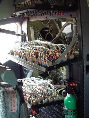
Behind the P6 Panel
|
||||||||||||||||||||||||||||||||||||||||||||||||||||||||||||||||||||||||||||||||||||||||||||||||||||||||||||||||||||||||||||||||||||||||||||||
| Just to prove that
electrics is not the exact science that engineers would have you
believe, check out this story from Suzanna Darcy, a Boeing flight test
pilot for 18 years: Systems that seem fine alone can interfere with one
another, she recalled testing a 737 (NG). When she switched the power
on, she heard the toilet in the lavatory flush. After confirming that no
one was in the lavatory, she switched the power on again. This time,
all the toilets on board flushed. The reason: interference between
electrical systems. |
|||||||||||||||||||||||||||||||||||||||||||||||||||||||||||||||||||||||||||||||||||||||||||||||||||||||||||||||||||||||||||||||||||||||||||||||
|
|
|||||||||||||||||||||||||||||||||||||||||||||||||||||||||||||||||||||||||||||||||||||||||||||||||||||||||||||||||||||||||||||||||||||||||||||||
Possible causes of Generator
Diagnostic Panel lights are as follows:
|
|||||||||||||||||||||||||||||||||||||||||||||||||||||||||||||||||||||||||||||||||||||||||||||||||||||||||||||||||||||||||||||||||||||||||||||||
The Power System Test panel (M400) Series -1/2/3/4/500 onlyShows the phases of the various AC busses in accordance with the following table:
|
|||||||||||||||||||||||||||||||||||||||||||||||||||||||||||||||||||||||||||||||||||||||||||||||||||||||||||||||||||||||||||||||||||||||||||||||
NG Series Differences  The functions of the above panel are all contained within the AC & DC Metering panel on the NG. The M400 panel space is now occupied by the Data Load Panel. |
|||||||||||||||||||||||||||||||||||||||||||||||||||||||||||||||||||||||||||||||||||||||||||||||||||||||||||||||||||||||||||||||||||||||||||||||
Electrical SchematicsThe following electrical schematics are included to give the reader an overview of the basic electrical configurations of the various series of 737. Please note that although these contain slightly more information than FCOM Vol 2, they are still a great simplification of the full system (particularly in the way I have represented the standby power switch relays). Furthermore there have been many different configurations over the years for different customers, so please do not assume that your particular aircraft match any of the following. | |||||||||||||||||||||||||||||||||||||||||||||||||||||||||||||||||||||||||||||||||||||||||||||||||||||||||||||||||||||||||||||||||||||||||||||||
Tuesday, 25 June 2013
ELECTRICS

Subscribe to:
Post Comments (Atom)
No comments:
Post a Comment