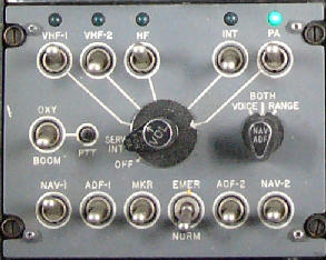
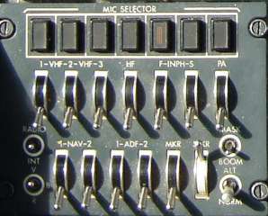
 Audio Control PanelThis type of ACP has cylindrical button volume controls, others have sliders.Radio/Int works in the same way as the rocker switch on the control column. ie in the INT position bypasses the mic selector to transmit on the flt interphone. The filter switch, Voice-Both-Range, allows better reception of either voice or morse identifiers on NAV & ADF radios. Check that this switch has not been left in the V position if you can't get an ident. Mask/Boom simply selects either mask or boom mic. Check this if nobody can hear you transmit - especially after your oxy mask mic check! Alt/Norm in the ALT position puts the ACP into degraded mode. If the Capts ACP is in degraded mode, he can only transmit on VHF1 through mask or boom and can only receive VHF1 at a preset level. The F/O's ACP in degraded mode is the same but uses VHF2. Note aural warnings will still be heard over the speaker. |
|||||||||||||||
 -200
ACP
-200
ACP
|
 ACP
with sliders ACP
with sliders |
||||||||||||||

VHF RadioMost 737's have three VHF radios and at least one HF radio. This unit allows for selection of any of those at this station. The TEST button is a squelch and is used to hear faint stations that do not have the strength to breakthrough. If you switch the panel OFF at the same time as TEST is applied this holds the test condition thereby allowing you to hear faint stations without having to hold down the test button - very useful for copying distant weather! |
|||||||||||||||
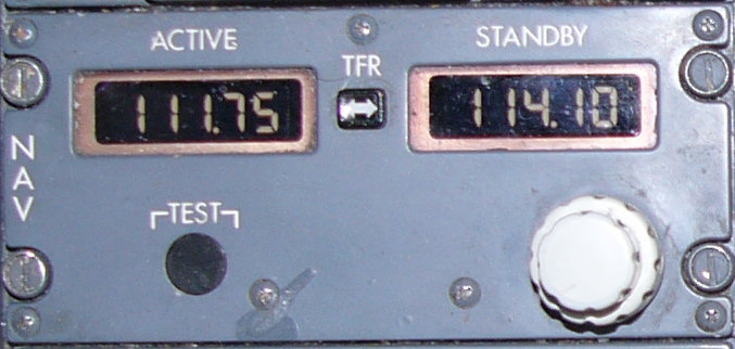  Photo Niklas Andreae Photo Niklas AndreaeNav RadioThere are very many different Nav radio boxes in the worlds 737's the second shown here is the new Multi-mode nav panel which is used to tune VORs, ILS, & GLS. More details about their use in the Navigation section. |
|||||||||||||||
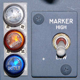 Marker BeaconsThe markers are pre-tuned to their 75MHz frequency and illuminate when overflown. The marker tone can also be heard if selected on the ACP. |
|||||||||||||||
Selective Calling, SELCAL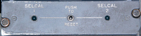 The SELCAL light will illuminate and a two-tone chime
sounds if the aircraft is being selcal’d on either HF or VHF. The SELCAL light will illuminate and a two-tone chime
sounds if the aircraft is being selcal’d on either HF or VHF.This particular panel is a very old unit and most operators have had to improvise the method of radio connections to it. Typically, in the past, diodes would be used to "OR" the VHFs together to illuminate one of the lights. Over the last 15 years, the vast majority of the SELCAL panels have a light for each of the radios (VHF-1, VHF-2, VHF-3, HF-1, HF-2) and in some cases, include the Attendant call, and SATCOM call. 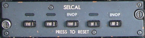 |
|||||||||||||||
The CVR records the headset and microphone of all 3 ASP's
and the ambient cockpit sounds all on
separate channels. The recordings
start with the first rise in engine oil pressure and go onto a 120 or 30min (as
fitted) continuous
loop tape until 5mins after last engine shutdown. In the event of an incident
crews are advised to pull the CVR c/b after final stop to avoid automatic
erasure. It is illegal to stop the CVR in flight.
The
CVR
is
located
in
the
aft
cargo
hold. |
|||||||||||||||
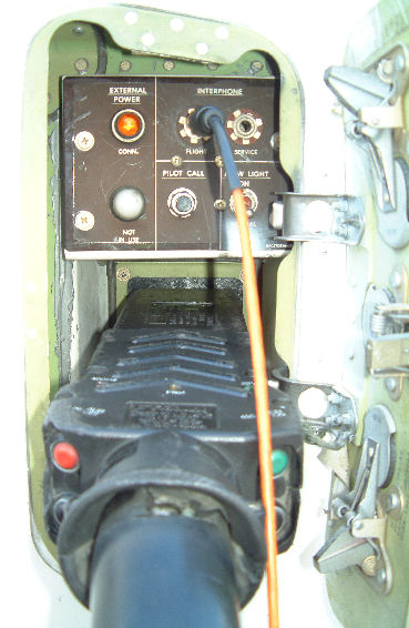 The External Power Hatch
is located beneath the F/O's DV window. It is used by groundcrew to
connect the Ground Power Unit and headset for pushback communications
with Flight Interphone.
The External Power Hatch
is located beneath the F/O's DV window. It is used by groundcrew to
connect the Ground Power Unit and headset for pushback communications
with Flight Interphone.The service interphone is used by engineers to communicate with the service interphone stations inside the aircraft. Note that the Service Interphone switch on the aft overhead panel must be switched ON for this use. There is also a pilot call button and a nose-wheelwell light switch to assist the groundcrew to insert the steering bypass pin. |
|||||||||||||||
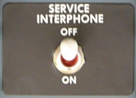
Service InterphoneThe switch on the aft overhead panel activates the external jacks to the service interphone system. Normal internal service interphone operation is unaffected by switch position. |
|||||||||||||||
|
|
|||||||||||||||
|
|
|||||||||||||||
|
|
|||||||||||||||
|
|
|||||||||||||||
 ACARS
ACARS
|
|||||||||||||||
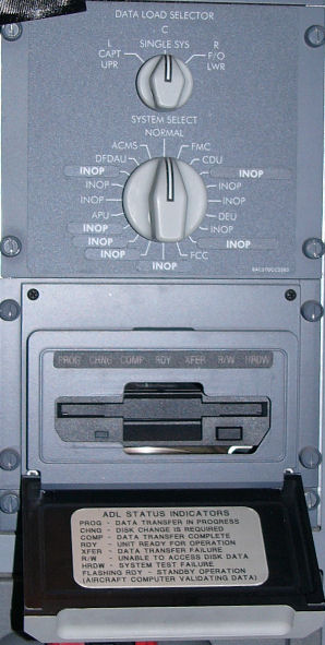 Aircraft Data
Loader - Used to load FMC database, download flight data eg FLIDRAS,
etc. Aircraft Data
Loader - Used to load FMC database, download flight data eg FLIDRAS,
etc. | |||||||||||||||
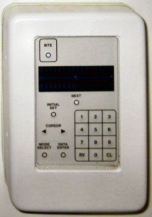 IFE
BITE panel. Located above door 2R IFE
BITE panel. Located above door 2R |
|||||||||||||||

Antennae
Antenna and static discharge wicks should be inspected
carefully on the walkaround for integrity and burns, especially if lightning or
St Elmo’s fire has been observed.


Please note that the above location diagrams are only a
guide as the antenna fitted depends upon the customer avionics options.
Eg some NG's
do not have ADF but do have SATCOM or IFTS/Airphone.
Limitations
There are various frequencies listed in the limitations
section as not to be used. These are due to interference from other systems. For
instance the EEC's affect VHF 120.00Mhz, there is a service bulletin (SB
737-73-1010) which will eliminate this. The HF frequency limitations are the
result of interference caused by cabin entertainment systems.
No comments:
Post a Comment